CAE (Comprehensive Analytic Engineering ) , Inc.
CAE SETS (Structure Engineering Turnkey System): True #1

PrePre_2 (PLOTREDO) TUTORIAL
Preprocessor of Preprocessors _2

At Mapped working drive X:, double-click Folder Prepre_2 as shown below:

File prepre2d.gif

At Folder Prepre_2, double-click Xprog.exe as shown below:
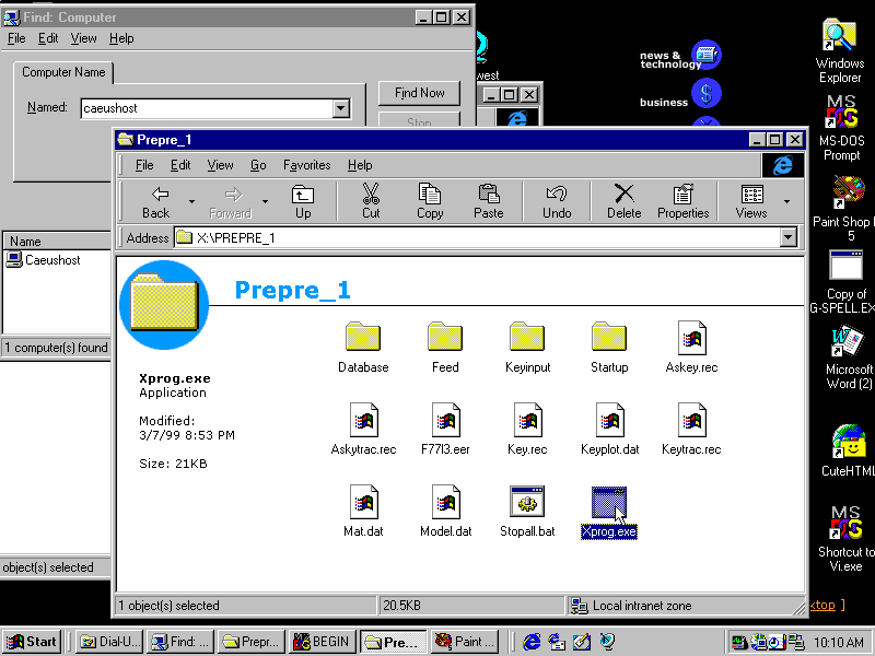
File xprogexe.gif

From the above graph for this example:
1) MODEL.DAT is premade/existing to define the range of screen scope with
2) TWO joint coordinates B1 and B2 as shown below:

$ MODEL.DAT FILE
$ NODE X-VALUE Y-VALUE Z-VALUE BOUND. CONDITION
$ ------ ------- ------- ------- ----------------
     B1         0.            0.         -20.   1
     B2       500.       500.      -20.   1
   END DATA

If it had been from BLANK SCRATCH, the Program would have prompted you to make a selection as shown below:
Thus, the MENU below will NOT appear in the DIALOG SEQUENCE for this case.
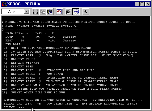
File modeltmp.gif


Then, the Program will read:

  1. First line of KEYPLOT.DAT TEXT File for RUN TIME DYNAMIC PARAMETERS.
  2. SETPACE.DAT TEXT File for screen graph speed.
  3. KEY.REC File,which PREPRE_1 made or you converted from text editing.
  4. MAT.DAT TEXT File (always premade) if needed.
  5. Section Data Base (AISC TEXT File provided) that you provided if needed.

The Program is METERED to produce a BILLING RECORD when it finishes.


The Instructions with screen graphs below show you how to generate MODEL.DAT File. (Note: Maximize Windows for clarity if needed.)

PROGRAM READS KEY.REC ONE-KEY-BUTTON FILE
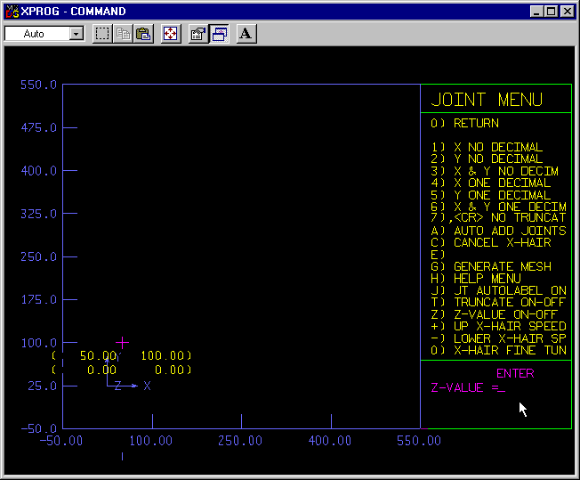
File graf001.gif

After Cross-hair from this menu has generated FIRST BASIC POINT,
it prompts you for Z-coordinate input.
You press [Carriage Return] to give 0. for Z value.
(Note: It can be any other appropriate number)

Generated THREE BASIC POINTS
(2-D and 3-D Minimum Requirement)
You generate more than THREE for ODD SPACINGS situation.
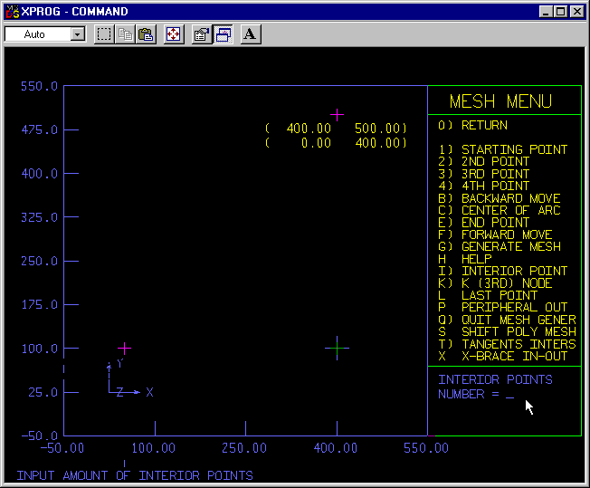
File graf002.gif

It prompts you for Amount (Number) of INTERIOR POINTS Input along X-direction.
You press 4 and then [CR]
(Note: It can be any other appropriate number)
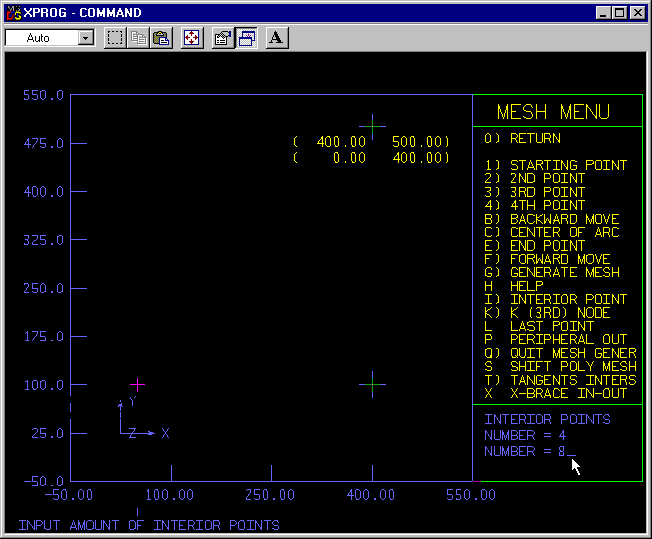
File graf003.gif

It prompts you for Amount (Number) of INTERIOR POINTS Input along Y-direction.
You press 8 and then [CR]
(Note: It can be any other appropriate number.)
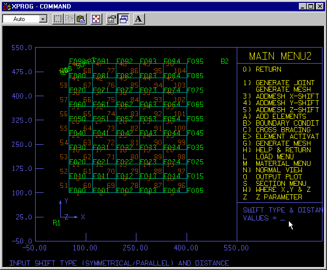
2-D MESH GENERATED with GRID SYSTEM NODE NOTATION

NOTE: Notation for a NODE gives clue to its coordinate values

File graf004.gif


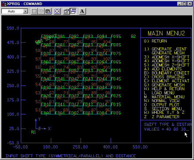
It prompts you for Z-direction expansions for a 3-D frame

File graf005.gif

You input 40 80 30 and then [CR]
[NOTE:The input items can be more than three. (Subject to limitation Vendor sets from pratical consideration, currently 15 or so.) Also the spacing can vary.]

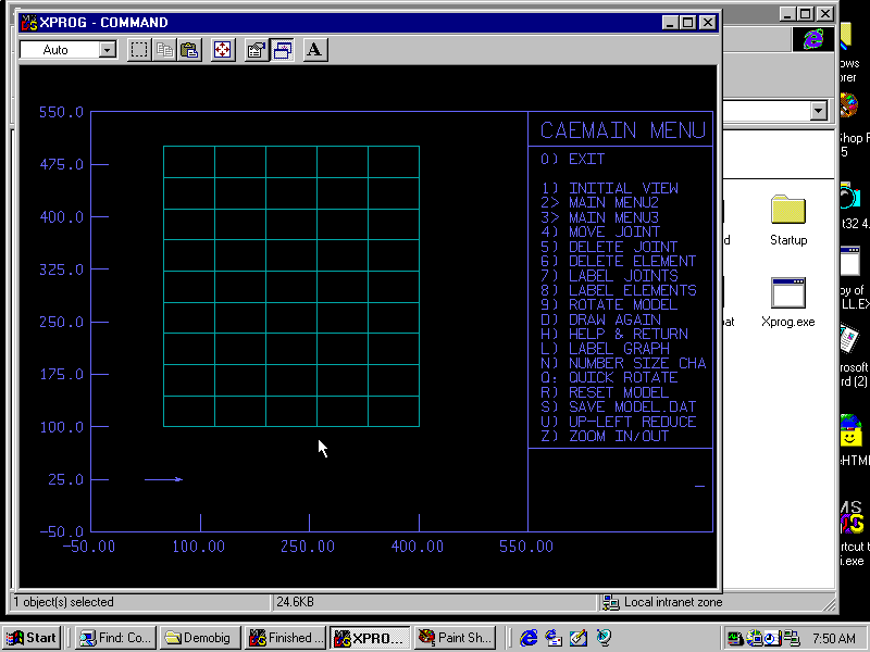
3-D MESH GENERATED BUT IN SUPERIMPOSED ELEVATION VIEW

File graf006.gif


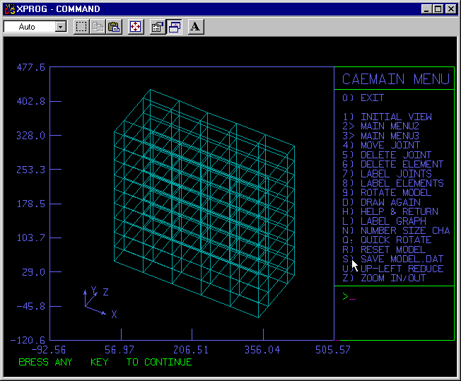
NEXT TO OBTAIN 3-D ISOMETRIC VIEW

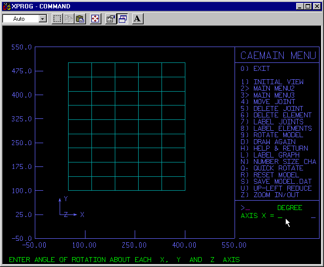
File graf007.gif

It prompts you to input angle of rotation about X-axis.
You input for X-axis -45 [CR]

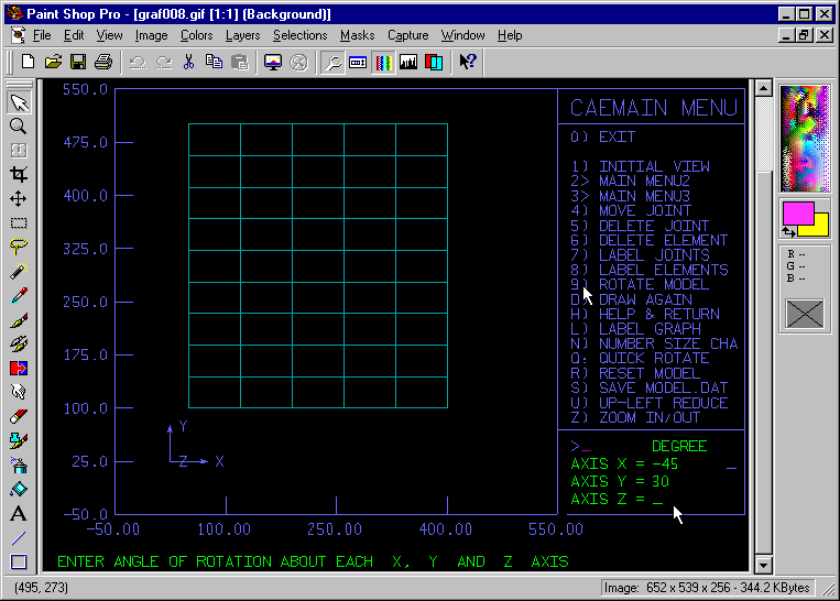
File graf008.gif

You input for Y-axis 30 [CR]
You input for Z-axis [CR]

3-D MESH ISOMETRIC VIEW OBTAINED

Note: To capture/print screen graph, hold down [Alt] key and press [CR], you can toggle out to Windows Mode. (and later on toggle into Graph Mode again. It will not affect the Prepre2|Prepre1 operation push-one-key sequence)
  • Many softwares from third partie available. (one or several from CAEinc)
  • Windows 98/ME/2000/NT all capable too.

    File graf009.gif

    At this point the SAVED MODEL.DAT File is correct for geometry.
    [In this example, Prepre2 Tutorial ends the session here.]
    It propmts you to PRESS any key to continue.
    You press the space bar.
    REMIDER:
    For a complex structure ,while work-on, to print screen graph(s) often is highly advisable. You can quickly modify/correct the geometry to generate/prepare correct data. The Program enable you to do key-in on screen-graph-spot for correction/input. This way the input data stream is continuous through completion. If you start a new task with a text editor it will take longer for a complex structure. (However, this example is a simple structure with only vertical and horizontal elelemnts, you do not have need to use such capability.)

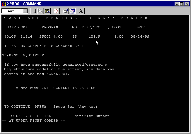
    GRAPH PROGRAM FINISHES and SHOWS BILLING INFORMATION

    (Note: For this run, 101.9 seconds from remote dual-up)
    File graf010.gif

    Computer keeps a record internally also.
    You can make a paper copy by print screen for your record.

    (242 NODES; 597 ELEMENTS; 845 INPUT LINES in 101.9 second.)

  • Practically, most of structures in this category from a simple beam to a big sky scraper can be this fast, namely from 40 seconds to 180 seconds.
    The time is spent mostly waiting to read ONE-KEY BUTTONS you press interactively.
    PREPRE_1 reads ALL ONE-KEY BUTTONS interactively vs PREPRE_2, mostly from
    KEY.REC File.
    PREPRE_2 takes up 60-90 percent of time to automatically read pure ONE-KEY-BUTTONS File (KEY.REC).
    Thus, it saves some time as compared with PREPRE_1.
    Both PREPRE_1 and PREPRE_2 save time with SEVERAL ORDERS OF MAGNITUDE as compared with others that require KEY-IN data from blank scratch.


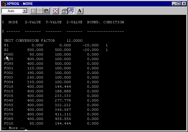
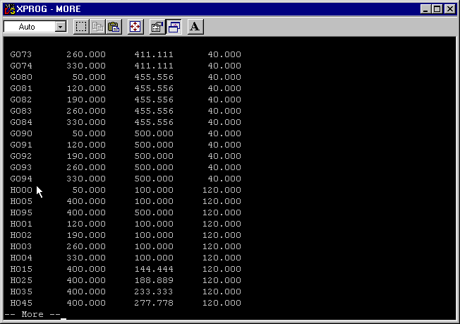
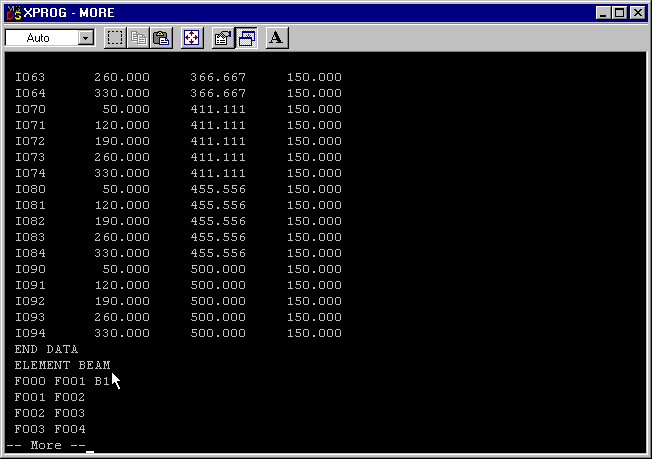
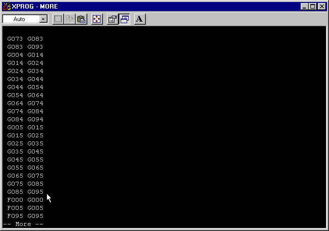
    PARTIAL MODEL.DAT FILE LIST

    ADDITIONAL QUALITY CONTROL AND MAN-POWER SAVING FEATURES over STRUDL

    • NODE notations give clue to their coordinate values.
    • ELEMent BEAM needs NO MANUAL numbering as input file to HyperSTRUDL.
      • 1ST line below for HyperSTRUDL plain input; 2ND line modified from STRUDL
      • F001 F002
      • 2 <$ F001 F002

    File graf011.gif


    File graf015.gif


    File graf021.gif


    File graf022.gif


    Back to the CAE Home Page


    This page was last updated on August/28/1999 and Oct. 14, 2003 .